Well, the J2X blog has been having some amazing posts and images of their progress in readying the first J2X engine unit for testing, with both the engine and the test stand stand getting close to ready. Hopefully, things will continue to go well, and we might soon see this engine fire, the first good-sized hydrogen/oxygen engine (important for upper stages) to be developed in the US in quite some time.
 |
| J2X engine unit under assembly |
 |
| Test stand A2, with J2X mass simulator in place |
I'm not sold on the need for the J2X or some of the proposed applications. I've heard some arguments for it, I've heard some against, and none have completely convinced me. Still, it's really exciting getting the inside look at the development process that the J2X blog has been offering. The J2X is a modification of the J2, originally developed as the upper stage engine to send the Apollo missions to the moon. However, since changes have taken place in manufacturing techniques and theory in the days since the Apollo program and the J2 has been out of production for almost 35 years, the J2X is less of a modification of an old design and more a new engine that uses the same basic design. One example of this inspired the title of this post, the Shiny Metal post about exploring making use of additive manufacturing techniques to speed up construction and lower costs.
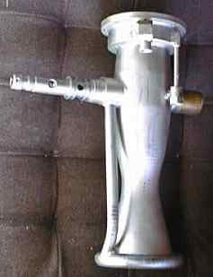
So...what does this all have to with me? Why post about it on Engineer in Progress? Well, it's cool new stuff in aerospace, and I like talking about that. However, it also reminds me of something that I've been working on with the University of Dayton Advanced Rocketry Team (UDART). I've been getting into the organization this year, and the last few days we've been doing some work on our own engine. If you look at my profile picture up on the top right, you'll see me holding the club's LR-101 rocket motor, taken at a presentation they did early in the year before I got involved (actually, that presentation was part of how I ended up getting involved, but that's not worth talking about).

The LR-101 is a liquid rocket engine that burns kerosene and liquid oxygen, and produces about 1,000 lbs of thrust. Just like J2X, the LR-101 has a rich history--while the J2 was developed as an upper stage engine for Apollo, the LR-101 was intended as a vernier steering motor for the Atlas missile--note the welded patches on the combustion chamber where the old gimbal system used to attach (see the image below for what an LR-101 looks like with that).
However, while the J2X is under development and testing to qualify new modifications, we want to test this engine to ensure it's still got enough of the old performance left for the application we'd like to use it in--as the main engine of a sounding rocket intended to reach up to 30,000 feet. To do this, we need to put the engine on a test stand, instrument the engine, and static fire it. The mount at the bottom of the engine in the picture above is part of the mount to the stand. Since I've been a bigger part of the team, I've made getting the test stand ready a priority of mine, and the last few weeks as I've had time away from Aerodesign have paid off handsomely.
 |
| UDART LR-101 test stand. Click Image for full size |
The entire frame is designed so that we can load it into a pickup truck and move it to a site where we can actually fire the engine, as opposed to our lab next to Five Guys and Panera on Brown Street. At the site, we can then tie it down securely, but the main engine connections and others don't require further work at the site beyond verifying functionality. The way the system works is diagrammed below.
 |
| Digram of Propellant Systems |
There are three tanks, one of the kerosene fuel, one of the oxygen, and one of high-pressure nitrogen. The nitrogen serves to pressurize the main tanks and force the reactants (the kerosene and oxygen) into the engine to be reacted. To fire the engine, we first open the pressurization valve to bring the tanks to pressure, then open the propellant valves and ignite the engine. The actuators for the valve assemblies can be seen above, though the ball valves themselves are sort of hiding behind the engine mounting plate. A better view of this section can be seen below.
 |
| Test stand from upstream. The valve assembly is at the bottom center of the photo. |
The valves we use are ball valves, and to ensure proper operation, we have to make sure that the actuator moves them from completely closed to completely open, but doesn't try to go beyond these limits (to avoid deflection of the frame). To do this, we first adjusted the fitting between the actuator rod and the valve rotation link so that it is in the fully closed position when the rod is fully extended, then checked how long the rod needed to be when the valves were fully open. To stop the rod from getting any shorter than this, we have to insert a stopper, shown below.
 |
| Spacer/Stopper Rod, Checking Length After Cutting |
This consists of a cylindrical piece of metal that goes around the actuator rod. When the rod retracts to the length we want to be the minimum (and corresponding to fully-open valves), the stopper will be stuck between the actuator cylinder and the fitting on the end of the rod, preventing any further retraction. To make this, we took a piece of metal stock that had the right outer diameter, and machined it to have the proper internal diameter. However, while the stock we had did have a hole in it, it was not only too small for the actuation rod to fit through, but in fact too small for the smallest boring bar we had for the lathe to fit into.
 |
| Original stock center hole size |
 |
| Required final inner diameter |
Thus, what we had to do was first drill out the center hole with a drill bit, then further increase the internal diameter with the boring bar until the internal hole was large enough to fit around the rod. However, there was one last issue--the boring bar was too short to fit all the way through the stopper size we needed. When we realized this, we had already spent several hours messing with the stand Saturday, so we decided to call it a night instead of taking the time to do the ten or so cuts it would take to do the other side.Thus, tomorrow, we have to turn the stopper around, and finish boring out the last few centimeters of the other side Actually, the images taken above are of the two ends of the same piece that will become the stopper, so you can see clearly what we have to do. Still, once this is done, we will be able to finalize the actuators, assemble the plumbing to the tanks, and leak test and check the entire system. Then, we just have to take the whole thing apart and clean it to be ready to test. The whole thing is a lot closer to operational than it used to be, and I can't wait to see the job through to static firing.
No comments:
Post a Comment