Tuesday, October 25, 2011

Ideas That Might Hold Water (Or at Least LOX)

Any regular readers I may once have had may notice it's been a bit sparse around here lately. In short, it's been because between classes, my OSGC research, and other projects, this blog has fallen down my list of priorities a bit. I'm planning to go into how that's been going in another post later, but the main reason for this post is that I got re-interested in an old idea of mine today and I thought it'd be worth writing up for Engineer in Progress. So let's talk about the SpaceX Dragon, and how I think it could be converted into a reusable fuel tanker for a fuel depot architecture.

I've very interested in the potential of depots in exploration architectures. It allows reusable orbit-to orbit spacecraft to be used for transits to the Moon or Mars, and allows missions that would require superheavy-class launch vehicles without depots to be staged with nothing more than existing or planned launchers like SpaceX's Falcon Heavy. For instance, on an Apollo lunar mission, the total hardware mass was only around 30 metric tons, but the total initial mass delivered to Earth orbit was 127 metric tons or so. This means that with a depot system for storage and transfer of cryogenic propellants, an Apollo-class mission could have been undertaken with 4 launches of a 30 ton vehicle. The lesson here is interesting particularly because of the capabilities of the Falcon Heavy and Falcon 9 Block II rockets (roughly 50 and 15 tons respectively) and their relatively low costs compared with past vehicles.

However, the need to fill such a depot requires a vehicle to serve the depot, a tanker. This vehicle will have to be launched as payload on a rocket, then be maneuvered to dock with depot and offload propellant. This creates two options. The first is a dumb stage, a tank that is inject to an orbit close to the depot, then grappled by a reusable space-only tug and moved to the depot. This makes the tank light, cheap, and ultimately disposable. The other option is a stage that's smart enough to fly itself, eliminating the need for the tug. However, this makes the stage an automated logistics spacecraft and thus expensive. Thus, if possible, it seems that such as "smart" spacecraft should be reused if possible. 


In thinking about reuse of a "smart" tanker, I was inspired by the concepts for using modified Delta IV upper stages as depot components like the image shown above. It seemed like fairing over the tank structure could create a capsule-like shape. Covering this with a thermal protective system could allow a ballistic entry into the atmosphere for reuse. However, this require a lot of modifications, since the Delta IV 5-meter upper stage shown as a depot component in that image isn't intended for long-term use or reuse,. Thus, adding proper maneuvering control and thermal protection might be very challenging. Turning a lightweight tank stage into a capsule might be a bridge too far: too hard, too heavy, too expensive.

However, what about turning an existing capsule into a tanker? SpaceX's Dragon had always been my mental image of the final product due to the steep sidewalls that would be dictated by the Delta IV stage design. However, since liquid oxygen has a density of about 1.2 tons per cubic meter, a tank filling the payload margin for a Dragon would also roughly equal the pressurized volume. With a 16 ton-to-orbit Falcon 9 Block II and the 4.5 ton mass cited for Dragon on Wikipedia and in some SpaceX materials, this leaves room for 11.5 tons of LOX, which would have a volume of about 9.5 cubic meters. this fits nicely in the 10 cubic meters of pressurized volume on-board a Dragon. thus, it's possible that the only work needed to turn Dragon into a Dragon LOX Tanker would be to add insulation and an internal tank inside what is currently the pressure hull, and add systems to fill this tank on the ground and empty it into the depot on-orbit. The primary structure could remain largely unchanged, as could the Draco thrusters and the capsule's control systems. Dragon's thermal protective system has already been designed to be capable of multiple flight, so I think it's possible that after factoring in all the costs, this could be a competitive alternative to expendable "dumb tanks" both per-flight and on the more critical $/kg scale.
Dragon Pressure vessel being integrated with bulkheads for the un-pressurized hardware section containing thrusters and other equipment. In a Dragon Tanker, this pressure volume would contain the LOX tank.
As to why I suggest a single-fluid tank (LOX only) instead of carrying both a fuel and LOX, there's a couple of reasons. First, while the idea could work with two tanks (one for LOX, one for fuel), kerosene and methane are both less dense than LOX (70% and 37% as dense respectively) so a Dragon spacecraft carrying a full 10 cubic meters of mixed kerosene/LOX or methane'LOX might not be taking full advantage of the launch vehicle's capabilities, Liquid hydrogen is so much less dense (only 6% the density of LOX!) that it's not even worth thinking about. (On a side note, this low density is why despite the fact that only 16% of the mass of a hydrolox rocket's propellant is hydrogen, the hydrogen tank is usually several times the volume of the LOX tank. See the Space Shuttle external tank, the Saturn IV-B stage used in Apollo, or the Delta IV upper stages used in the depot shown above.) This means I don't think the added complexity justifies the gains. 

This is especially true in my mind in light of the fact that for almost all liquid rockets, LOX makes up far more of the mass than does the other fuel. For instance, 100 tons of fuels for a kerolox rocket would consist of only 30 tons of kerosene, while a similar mass of hydrogen/LOX fuels would be 16 tons of hydrogen. A depot storing LOX could serve to "top up" stages launched carrying fuel only whether they burned kerolox, methalox, or hydrolox, while being substantially less complex due to the need to only handle and store one fluid. 
Anyway, in short, Dragon is an existing multi-role vehicle that I think might adapt well to serving as a cheap, reusable LOX tanker as part of a depot-based exploration architecture. I think it'd be an interesting trade study to compare in more detail the cost per kg of fuel of a "dumb" expendable tank system versus a modified Dragon Tanker like I've described above, but I don't know that the data do do so is available publicly.

Monday, September 12, 2011

How I Spent My Summer Vacation (By Rob Davidoff, Age 20)

It has recently come to my attention that, despite the evidence to the contrary evidence of the post rate here at Engineer in Progress, I am in fact not dead. In fact, with the start of the school year, I’ve actually had time to do things, even! With that, I thought it would be worth bringing everyone up to date on my summer and what I’ve managed to get checked off of the To-Do List of All Dooms.

In this post, I’d like to talk a bit about what I did this summer (a topic that makes me feel like I’m making a presentation in second grade). As you may recall, I spent this summer as a test engineering intern at Ferno-Washington in Wilmington, OH. I meant most of the summer to write a post describing what exactly what that meant, what it involved, and what I felt I was learning, but unfortunately between my mom’s health issues, the commute to work, and other complications, I never had the time. So let’s start things with that.

"So what is test engineering?", I hear you ask (unless you're part of the 50% of my traffic that's just here for the pictures, in which case you'll be more interested in the diagram of the BA-2100 in another post planned for later this week). I'm glad you asked. Basically, test engineering is involved with the testing required to test various design concepts during engineering development, and then to validate design prototypes against internal and external standards to ensure that the final product can do what it needs to do. If design engineering is about making solutions to problems, test engineering is involved in picking the best solutions and making sure the solutions work as intended under varied conditions.

This meant a lot of dealing with paperwork, and a lot of dealing with standards. In doing this, I came to some realizations about the two. This summer at Ferno, my major responsibilities were processing test requests from design engineers, carrying out and documenting the testing, then preparing formal reports about the test, which meant I had a lot of experience with paperwork. In my ten weeks at Ferno, I participated in closing out about 30 tests, which included both ones I performed in addition to ones that had been performed prior to my arrival, but which had my boss had not had time to document himself. In both cases, while preparing the formal test reports, I depended extensively on photographic and written documentation of the events of the test. And the reports themselves had value: for many reports, we would refer during the test planning stages to setup descriptions of similar tests in the past to ensure that our methods were consistent with the past setups.

Standards also played a major role in my summer work at Ferno. In testing, the question that was always asked about a new test request was the purpose of the test--what was intended to be learned. Was it to compare several design solutions and find the "best"? Was it intended to determine whether a prototype was capable of performing as desired? In all these cases, standards played a critical role in planning the test and evaluating the test results. These standards could be regulatory, part of the standards that Ferno's products had to meet to be certified for use in the demanding conditions emergency equipment may encounter, or they could be internal standards to ensure that the product also provides users with the quality they rely on. In dealing with these standards in testing, I came to better appreciate the need to have such standards. Without a defined standard to test to, a test really isn't informative. The standards themselves must be meaningful (testing to proof or ultimate loads or simulating field conditions), but a test done to a meaningful standard is far more meaningful than one without a defined standard.

All in all, I really enjoyed my time at Ferno. I was lucky that most of my co-workers were friendly and easy to work with, and I feel like I made a valuable contribution during my time there. When I arrived, the test report backlog had grown to more than thirty reports, on the day I left it had been reduced to six, none more than a week removed from the date of test completion. I feel like I learned a lot more about the purpose of testing in engineering and what makes a test valuable, and I look forward to carrying these lessons on with me, both to the Aerodesign team this school year and on to other areas of my professional career. So, yeah, that's what I did this summer. I have more to say about what I've been up to since my last day at Ferno, but since this post is already pretty long, I'll leave it for another time.

Wednesday, June 29, 2011

Free Time? What Free Time?

It's been busy for me, between work and some health issues for my mom, so I haven't had as much time to blog as I might have liked. That's as far as I'll go towards making excuses for my lack of posts the last week or two. However, that's not to say I haven't been working on stuff, just not much and not for very long at a time, and I haven't had any time beyond those work periods to write about them. On that catch-up note, here's an entire project of mine I've yet to even have the chance to talk about here.

About two weeks ago, I was contacted by someone who wanted some help rendering something. You may have heard of the Nautilus-X spacecraft proposal, a design for a long-term reusable orbit-to-orbit vehicle, built in multiple launches using ISS operational experience. The most striking feature for many people is the centrifuge ring, which is spun to create the illusion of gravity. This tends to excite space fans, since centrifuges have this whole air of sci-fi about them, and yet are still plausible, except for all the messy little engineering details like making the plumbing and wiring work across a rotating interface or the effects on maneuvering of essentially having a 30 ton gyroscope mounted to your ship.
Nautilus-X, front perspective view showing centrifuge ring
Nautilus's centrifuge is interesting because it proposes to use inflatable structures for much of the ring. It consists of a rigid hub, connected by a rigid passage tube to a rigid ring section. The ring itself is a mix of such rigid sections linked by inflatable sections (the other two rigid sections are connected by extending trusses to the hub, and serve to help support the ring in spin). Compacted, it's a very tight package, and makes good use of the rigid components where rigid is of benefit and inflatable where inflatable is best. On-orbit, the trusses would extend the ring sections, then the ring would be inflated and fitted out with habitat equipment: sleep stations, communal living areas, perhaps a sickbay or other equipment where gravity would pay off. The idea is interesting, if a bit of what Robert Zubrin would call a "Battlestar," an over-complicated slightly over-built spacecraft, but it's a big dream and I like those. The images of a test centrifuge attached to the ISS as a tech demo especially appeal to me. I've often lamented the loss of the funding for the Centrifuge Accomadations Module, and the lack of really good data on the reaction of the human body to varying gravity levels (including prolonged sub-Earth levels, like a Mars colony might have) and the rotation rates possible before biology and gravity gradients become an issue. With these two pieces of data, it'd actually be possible to design a 2001-style station or a spacecraft like the Discovery (or indeed Nautilus) with some kind of artificial gravity centrifuge.

Demo Centrifuge at ISS
The person who contacted me asked if I might be willing to try to render a conceptual cutaway of the interior of the ring. I used to spend days in middle school doodling diagrams of spacecraft and drawing scale floor plans of them, so this appealed to me, especially since it'd be a nice chance to press my modeling chops. It seemed like a fun thing to try and do--design a possible interior in a relatively small-diameter rotating centrifuge. I should be clear that neither he nor I has any real idea of the internal layout of the Nautilus, I'm not sure one exists at this time, despite all the nifty images of the ISS demo module. Thus, the following is only my best guesses, and as much informed by the design of boats and mobile homes as by valid spacecraft design principles. I hope Winchell Chung can forgive the transgression the previous sentence represents, but it's about the best I can do for the moment. Engineer in progress, it says so in the title.

Anyway, so to start, I needed to establish the physical parameters of the ring. It has been stated in presentations of the concept to have a diameter of 60 feet, and from the image above, scaling from the core (stated in another slide to have a width of 6.5 m), the ring's minor exterior radius looks to be about 4 m or so. Taking into account inflatable walls with a thickness of 16 inches, on the order of Bigelow's designs, this produces an interior diameter of about 134" (Yes, Imperial units. Deal with it. I did.). This gives a volume of around 425 cubic meters, about right for 6 people's occupation for up to two years. It's worth noting that combined with timing this animation of Nautilus (yielding 10 seconds per spin, or 6 RPM), the ship is basically designed to yield Martian gravity: 1/3 Earth gravity.

Cross-sections of Ring
To create the interior of this ring, I defined a flat floor as shown above, based on a minimum overhead of 6 feet. I show a centerline passage of 36" and a passage going past a partitioned room (shown with 36" bed), with 30" of floor space, and some extra elbow room. I then broke down the ring into rooms using these arrangements, and created the design below in Adobe Inventor. The "roof" level is a 78" ceiling: enough to give some head room even for tall people like myself, but not quite towering. With all the area under the floor available for use by utilities, I think that when I get around to modeling a ceiling, it'll be much more of narrow enclosed (?) utility run along the middle than the illustrated flat surface at 78" above the floor, a duct as opposed to a drop ceiling.
Attempt at Nautilus Floor Plan
Click  Image for Full Size
After some refinements and modifications based on discussion with the person who requested the work, I was satisfied enough to begin rendering the ring in Inventor. I rendered each portion (cabins, heads, the mess/galley area, the gym, stowage, the lab and medical bays) separately, so I could assemble them in any order, and so that changes to any on of duplicated rooms like the heads or the cabins would be reflected in all of them with the click of a mouse the next time I opened the assembly. Some rendered animation of the model are below (my first attempt at it with Inventor and it kind of shows--note for future: floors and background should contrast more). I'm hoping to refine both the model and my method of showing it off a bit more, but I'm pretty happy with the start of it. 

View One (Click to play)

View Two (Click to play)

Tuesday, June 14, 2011

Good News and Bad News

So, as the title suggests, I have some good news, and I have some bad news that it'll be bringing with it. The good news is that as I mentioned last post, my summer suddenly became a bit busier than I was worried it might end up. After a lot of job searching, I accepted an offer of a summer position with Ferno-Washington Inc. of Wilmington, Ohio.


Wednesday, June 8, 2011

Imagined Images and Reality

So, you may already heard this (curse my sudden lack of free time!), but the STS-134/International Space Station images are finally in. The image NASA's been promoting the heck out of (and rightfully so, I think) is below, showing the station from the port side, with the shuttle and the station's truss and modules both very visible.

Click image for mondo big version
For those interested, many others from the same astounding  set can be found on the NASA.gov site here. Personally, I think I have enough new backgrounds to last for months if not years. (Also see the video here, for some more amazing content.).

This is truly an amazing and historic moment, but looking at it and thinking about why it is, it reminded me of an image I posted a while back here on Engineer in Progress. No, not Kieth McNeills's amazing model images of what an STS-133 flyaround might have looked like (now with side-by-side comparisons with the real thing on NASAspaceflight's forums here). Something earlier.

Is it the STS-71 Mir image, taken in a similar fashion to the ISS imagery sequence?

No, it's not. It comes from even slightly before that. See below:


That's not the ISS there. That's an artist's conception of the American Space Station Freedom, from the mid-80s to the early-90s, the station which morphed into the core of the American portion of the station. So the Shuttle-docking-to-station image has legs. Why? Because this is what the Shuttle was about, about building and servicing a large space outpost, where various types of science could be performed, from life sciences, materials experiments, astronomy (early SSF proposals included an attached telescope observatory), and technology demonstrations for revolutionary new space hardware (in it's day, they were looking at stuff like solar thermal power generation).

Basically, only in the last few years has the ISS has actually started to do that. The AMS-02 instrument is amazing, but it's only now at the end that it's finally flown. Proposals are circulating to test BEO technologies like VASIMR, inflatible habitats or closed-cycle life support systems on ISS (the ISS water-recycling system is sort of part of that, and that's been going for a few years now, I guess.). And now, finally, after almost 20 years, it's finally happening. That's what I see when I look at the images of Endeavor docked to ISS: the culmination of a 20-year dream.

What's next? Where does spaceflight go from here? I wish I knew. I wish anyone knew--the whole situation with the SLS (Space Launch System, a congressionally-mandated new heavy lift vehicle) is so convoluted, politically-and-emotionally-charged and multi-polar I don't think I can adequately state what the situation is, but it's there. There are also the multitude of dreams offered up by Bigelow, SpaceX, XCOR, Armadillo, Masten, Altius, and many other commercial space companies. In 20 years, which of these dreams will be a reality, and will it take all 20 to make it happen? I wish for as many of the former as possible, and hope not the latter on any. But we'll just have to see. I just wish the space program of the next decade could amaze me and my generation in ways the space program of the last 50 occasionally has amazed past generations, and continues to amaze those of us who care to research it. That's all I want to say, just go back up and enjoy all the links.

Wednesday, May 25, 2011

Mistakes Were Made

Longtime readers (let's pretend for a moment that such a thing exists) of this blog may recall past posts about Bigelow Aerospace, my excitement about their technologies, and my attempts at creating a Transhab Module Calculator capable of roughly approximating possible Bigelow modules. Today, Bigelow broke it's veil of corporate secrecy and allowed a copy of some charts the founder, Robert Bigelow, presented at the International Space Development Conference to be posted at a few sites. Engineer in Progress was not one of those sites, so I can't present that data, but what I can present is this finely-crafted hyperlink to the presentation on SpaceRef, one of the sites that was allowed to post it.

Naturally, after I got done geeking out about the technical details, one of the first things I considered was the specifications presented for the BA-2100 (now dubbed "Olympus," which I think is appropriate for a module that has greater volume than Skylab, Mir, and the International Space Station added together) and whether they fit my calculator's predictions. The results were troubling: the calculator underestimates the module's volume by almost 300 cubic meters, and overestimates the mass by almost 20 metric tons even on my lowest predicted equivalent density.

This error was pretty significant, and so I decided to double-check the calculator against the provided figures for the BA-330. This module was one of the ones I used to calibrate the calculator when I originally created it, so it was perhaps even more troubling that the predictions were also off for the BA-330: The volume was low by almost 100 cubic meters, an underestimate by almost a third.

Therefore, until I've had a chance to look over the new data and diagrams, re-examine my assumed model parameters, and put everything together, I'm retracting the model. I'm going to have to figure out what to do about the calculator (what's wrong, whether I can fix it, and what to do in the meantime), but I wanted to put this out there.

tl;dr: I've found some mistakes in my model based on new data. It's down until I can fix them to my satisfaction.

Monday, May 23, 2011

Been So Long: Soyuz Fly Around at Last!

Well, I know it's been a while since I checked in--I've been busily trying to figure out what I'm going to do this summer. Getting turned down for co-ops all day is hard work. Anyway, I've also been avidly following the STS-134 mission, which featured the installation of the AMS-02 experiment unit on the station truss, and an unexpected but welcome addition: the Soyuz fly-around photo opportunity originally scheduled for STS-133.


On that flight, the Soyuz was the first of a new type, which meant that the Russians did not feel comfortable using it for the proposed photo. However, the Soyuz that is today being used is of the older type, and as a result even as I write this the Soyuz is separating from the station and backing off to take images of the now-finally complete station (well, except for the Russian MLM and node, anyway) and the Space Shuttle Endeavor on that vehicle's final flight. Astronaut Paulo Nespoli will be taking pictures and imagery of the station over the next half-hour or so. For more information, I recommend checking out NASA TV and Nasaspaceflight, my favorite place for space news updates. Engineering imagery of the station from the Soyuz are currently showing on NASA TV, and it's a great prelude of the full images we should get from this unique and historic opportunity.


Soyuz has rolled to re-orient station in camera view, station about to begin a maneuver to give Soyuz a better view of the station. Video apparently also being taken, which should be astounding.


That maneuver now in progress:


Pluming visible on the Soyuz as it maneuvers to keep station.


The imagery from the cameras Nespolia is operating should be amazing, just the engineering views from Soyuz are amazing. Can't wait!

Tuesday, May 10, 2011

I've Been Working on the Railroad

Just to pass the time away, of course. Anyway, I reserve the right to use Engineer in Progress to ruminate on ideas I like, and last night I saw a really interesting one. Ray MacVay, from Blue Max Studios (makers of the hard-scifi RPG Tales of the Black Desert), made an interesting post entitled Artificial Gravity and What Rollercoasters Can Teach Us, and it solidly engaged what someone of my acquittance once called my "turbonerd" mode. The proposal is to use self-propelled train-like cars moving around a fixed circular rail for large spin-gravity spacecraft, instead of a large rotating structure. I'm not really explaining it well, and he does a much better job, so...go read the original post. I'll wait.
Seriously, go check it out. It has pictures.
Done? All right, let's talk the engineering of such a system. First of all, I like a lot about it. Air doesn't need to cross the spin division because entire cars do, presumably each with on-board life support, water reprocessing, and that stuff. Power and data are a bit trickier--unless the cars have their own on-board power generation, then electrical power will still have to be sent to the cars with slip rings, and data will have to be sent from car to car either with a wireless network or (if wired is preferred) another slip ring setup. Still, it's an interesting modular system. Still, there's one or two things that need work.


Monday, May 2, 2011

Not-So-Shiny Metal

Well, the J2X blog has been having some amazing posts and images of their progress in readying the first J2X engine unit for testing, with both the engine and the test stand stand getting close to ready. Hopefully, things will continue to go well, and we might soon see this engine fire, the first good-sized hydrogen/oxygen engine (important for upper stages) to be developed in the US in quite some time. 

J2X engine unit under assembly
Test stand A2, with J2X mass simulator in place
I'm not sold on the need for the J2X or some of the proposed applications. I've heard some arguments for it, I've heard some against, and none have completely convinced me. Still, it's really exciting getting the inside look at the development process that the J2X blog has been offering. The J2X is a modification of the J2, originally developed as the upper stage engine to send the Apollo missions to the moon. However, since changes have taken place in manufacturing techniques and theory in the days since the Apollo program and the J2 has been out of production for almost 35 years, the J2X is less of a modification of an old design and more a new engine that uses the same basic design. One example of this inspired the title of this post, the Shiny Metal post about exploring making use of additive manufacturing techniques to speed up construction and lower costs.

So...what does this all have to with me? Why post about it on Engineer in Progress? Well, it's cool new stuff in aerospace, and I like talking about that. However, it also reminds me of something that I've been working on with the University of Dayton Advanced Rocketry Team (UDART). I've been getting into the organization this year, and the last few days we've been doing some work on our own engine. If you look at my profile picture up on the top right, you'll see me holding the club's LR-101 rocket motor, taken at a presentation they did early in the year before I got involved (actually, that presentation was part of how I ended up getting involved, but that's not worth talking about).


The LR-101 is a liquid rocket engine that burns kerosene and liquid oxygen, and produces about 1,000 lbs of thrust. Just like J2X, the LR-101 has a rich history--while the J2 was developed as an upper stage engine for Apollo, the LR-101 was intended as a vernier steering motor for the Atlas missile--note the welded patches on the combustion chamber where the old gimbal system used to attach (see the image below for what an LR-101 looks like with that).

However, while the J2X is under development and testing to qualify new modifications, we want to test this engine to ensure it's still got enough of the old performance left for the application we'd like to use it in--as the main engine of a sounding rocket intended to reach up to 30,000 feet. To do this, we need to put the engine on a test stand, instrument the engine, and static fire it. The mount at the bottom of the engine in the picture above is part of the mount to the stand. Since I've been a bigger part of the team, I've made getting the test stand ready a priority of mine, and the last few weeks as I've had time away from Aerodesign have paid off handsomely.

UDART LR-101 test stand. Click Image for full size
The entire frame is designed so that we can load it into a pickup truck and move it to a site where we can actually fire the engine, as opposed to our lab next to Five Guys and Panera on Brown Street. At the site, we can then tie it down securely, but the main engine connections and others don't require further work at the site beyond verifying functionality. The way the system works is diagrammed below.

Digram of Propellant Systems
There are three tanks, one of the kerosene fuel, one of the oxygen, and one of high-pressure nitrogen. The nitrogen serves to pressurize the main tanks and force the reactants (the kerosene and oxygen) into the engine to be reacted. To fire the engine, we first open the pressurization valve to bring the tanks to pressure, then open the propellant valves and ignite the engine. The actuators for the valve assemblies can be seen above, though the ball valves themselves are sort of hiding behind the engine mounting plate. A better view of this section can be seen below.

Test stand from upstream. The valve assembly is at the bottom center of the photo.
The valve assemblies have been the focus of work for a while, first getting the pressurization actuator and valve mounted to the stand, and now refitting the main valves and getting them set up. I spent the last two meetings getting the kerosene valve (on the right above) properly and securely mounted to the frame of the stand so that it didn't move and was properly aligned with the oxygen valve next to it. This is required since the two are operated by a single hydraulic actuator--this means that if properly set, the two will be perfectly in-sync, but getting them synced and set up is a lot of work. Saturday, we finished that, mounted the engine as is shown above (including spacers representative of the load cells we'll use to measure the thrust of the engine when we test it), and started work on zeroing the valves.

The valves we use are ball valves, and to ensure proper operation, we have to make sure that the actuator moves them from completely closed to completely open, but doesn't try to go beyond these limits (to avoid deflection of the frame). To do this, we first adjusted the fitting between the actuator rod and the valve rotation link so that it is in the fully closed position when the rod is fully extended, then checked how long the rod needed to be when the valves were fully open. To stop the rod from getting any shorter than this, we have to insert a stopper, shown below.

Spacer/Stopper Rod, Checking Length After Cutting
This consists of a cylindrical piece of metal that goes around the actuator rod. When the rod retracts to the length we want to be the minimum (and corresponding to fully-open valves), the stopper will be stuck between the actuator cylinder and the fitting on the end of the rod, preventing any further retraction. To make this, we took a piece of metal stock that had the right outer diameter, and machined it to have the proper internal diameter. However, while the stock we had did have a hole in it, it was not only too small for the actuation rod to fit through, but in fact too small for the smallest boring bar we had for the lathe to fit into.

Original stock center hole size
Required final inner diameter
Thus, what we had to do was first drill out the center hole with a drill bit, then further increase the internal diameter with the boring bar until the internal hole was large enough to fit around the rod. However, there was one last issue--the boring bar was too short to fit all the way through the stopper size we needed. When we realized this, we had already spent several hours messing with the stand Saturday, so we decided to call it a night instead of taking the time to do the ten or so cuts it would take to do the other side.Thus, tomorrow, we have to turn the stopper around, and finish boring out the last few centimeters of the other side  Actually, the images taken above are of the two ends of the same piece that will become the stopper, so you can see clearly what we have to do. Still, once this is done, we will be able to finalize the actuators, assemble the plumbing to the tanks, and leak test and check the entire system. Then, we just have to take the whole thing apart and clean it to be ready to test. The whole thing is a lot closer to operational than it used to be, and I can't wait to see the job through to static firing.

Friday, April 29, 2011

Shooting Gumballs

So, this is a recycle in a way. In the dim and distant past before I had a blog (read: last summer), a friend and I spent an interesting afternoon working out the answer to a scenario we came up with, and I thought it was fun, so I'm posting it here at Engineer in Progress. Let's say NASA and commercial comes through, the whole shebang. 4 commercial crew vehicles funded to completion by CCDEV (SpaceX Dragon, Boeing CST-100, SNC Dreamchaser, and Blue Origin's....thing). Between NASA and commercial, 4 man-rated US launchers (SLS, Atlas V, Falcon 9, Falcon Heavy). ISS is fully utilized, Bigelow gets things going on a commercial station, Astrobotic goes to the moon and wins the Google Lunar X-Prize (or some other comparable team does).

But you don't work for any of those companies. You don't build launchers, or capsules, or stations, or unmanned landers. You work for Space Supply Corp, Inc, Ltd and your division is bidding on a vending machine contract. Specifically, you're bidding to refill these critical pieces of equipment:
That is, gumball vending machines. Well, a version of them that doesn't use gravity feed. This isn't 2001, we don't have artificial gravity! This is near-term gumball-machine resupply contracting, after all. So...how much does an astronaut need to feed in to get out his gumball? Glad you asked!

The first question is shipment method. The average 1" gumball consists of a spherical shell about 1/8" thick, surrounding a central cavity that is approximately atmospheric pressure. This central cavity poses a problem: on the ground, the gumball does not experience a significant net pressure across the shell, since the air inside and outside are pretty similar (off by maybe a few kPa depending on the weather and the altitude of the ambient conditions of manufacture and measurement). In orbit, though, the gumball center has a full atmosphere inside, and a vacuum outside. Thus, it's acting like a pressure vessel, with the pressure inside being like being 30 feet underwater. If the gumball shell is not capable of taking the stresses of this, then the shell will fail, and either simply rupture or pop like popcorn (hence the highly technical term "popcorning"). The Space Shuttle External Tank's anti-ice insulation (which is made up of similar closed cells of foam) would do the same after time in space, which is why no studies for a Skylab-style wet lab were ever really considered seriously--huge risk for orbital debris.

So, if the gumballs aren't strong enough, they pop. How do you know if they are? Engineering! The material stresses on a spherical thin-walled pressure vessel are as below.


Sigma (the o with the line on the left) is the stress on the material. If this exceeds the maximum material properties of un-chewed gumball (chewed gum is over course deformable, which would change things in ways I'm not entirely trained to handle at the moment, but thankfully Space Supply Corp. Inc. Ltd does not supply NASA with ABC gum), the shell will break. In the equations, p is the pressure, so here it's 101 kPA (atmospheric in kiloPascals, the metric unit for pressure). The t is thickness, and the radius is r. Keep these units consistent, and they'll cancel out leaving just a ratio. (For the record, the radius-to-thickness ratio for 1" gumballs is slightly too large for the thin-wall approximation according to rules of thumb. It's 4:1, when 10:1 is supposed to be the max. But you get free engineering secrets for gumball shipment, you take my baseless assumptions.).

Calculating, the material stress is 404 kPa. So...does the gumball pop? Unfortunately, I can't find any research on the material properties of unchewed gum (attention scientists!), but this is a required strength something like 1/2th the minimum strength of rubber, so I feel confident in saying it has a good chance of working. This is nice, it means you don't need to use precious volume inside a pressurized transport like Dragon, Cygnus, CST-100, Soyuz, Progress, whatever, you just ship up your gumballs in a bag in Dragon's trunk, or the HTV external pallet bay, or something like that. You'll need an astronaut to grab it with a robot arm or snag it on an EVA to bring it in, but hey, it works.

SpaceX Dragon Approaching ISS
Unpressurized cargo like gumballs can go inside the cylindrical trunk section.
So, now we have the shipping requirements (unpressurized transport, some minor details on receiving). What's the cost? The current Falcon 9 carries 10.5 tons to orbit, but the version coming with the Merlin 1D upgrade is supposed to increase that to about 16 tons. Both are to cost about $56 million. This is a price of either $5,333 per kg or $3500. Wikipedia says Russia's Proton costs about $4400/kg. I'm not running numbers for the Atlas V or Delta IV, I can tell they will be worse since they cost more than Falcon by a factor of 4 or more for similar base payloads, and the pricing doesn't get better for Heavy versions. Falcon Heavy, on that note, is supposed to get down to $2200/kg.

So, what does this all mean for our gumballs? A 16 lb bag of 1" gumballs on Amazon costs roughly $30 (though the actual specs at the bottom say 17 lbs...odd), and contains 850 balls. Thus, each masses about 8.75 grams. Since the bag comes included in this mass and gumballs are probably vacuum-rated, there's no further shipping mass. So, cost to fly is easy if you completely ignore any cost-sharing or free-rides with other customers: Multiply the per-kg launch cost by the mass in kg of one gumball, and find the cost to user on orbit. For Falcon 9 currently, this would be $46.66, or $30.63 on the Merlin 1D variant that's supposedly coming soon. The Russian Proton workhorse would cost you $37.6 dollars per gumball, while the Space Shuttle is in the range of $291.67 per ball. Falcon Heavy's goal price would see a gumball representing a cost of $19.25. However, while the astronaut is carefully feeding those 77 quarters into the little slot and cranking the handle, note the shipping markup: the cost to Space Supply Corp, Inc, Ltd is only $30 a bag for 850, or about 3.5 cents per gumball, or a shipping and handling markup of about 5400%. For the record, this also means that the 25 cent gumballs you see so often are selling for a retail markup of 200%.

However, the gumball isn't a great metric for spacecraft themselves, just an example of the costs of shipping even a relatively tiny but imaginable payload--this same economics applies to every T-shirt, can of tuna, and bag of wet-wipes sent to the ISS crew and any potential future space exploration. Cheap to supply, expensive to ship. Spacecraft are a bit different, since even a small spacecraft (a bit heavier than a backpack with a few engineering texts in it) might contain several million dollars of specialized components, plus the spreading out of the cost of integration, testing, design and development before selection of a final design....it's easy for me to design something like this costing $10 million that costs no more than $50,000 to launch to orbit where spacecraft cost is only half a percent of total cost. However, any base needs some kind of supplies, and these will include a large portion of the cheap-to-buy, expensive-to-ship variety I mentioned. ISS uses a good amount of food and water, and when HTV-2 burned up on return from the ISS earlier this year, a large part of the trash it carried was foam that had ridden to orbit wrapped around science experiments.
Astrobotic Lander
110 kg of payload to surface available--for a price
As a final exercise for the reader, the Google Lunar X-Prize team Astrobotic has a publicly posted payload planning guide that says a base price of $1.8 million per kg. Find the cost of a gumball delivered to the lunar surface. Highlight for answer:  $15,700 or so. A lunar gumball costs about the same as four tons of supply-cost gumballs, 62.8 thousand Earth gumballs, or about 424 orbital gumballs.

Wednesday, April 27, 2011

Field Reports and Endings

Well, it's all over. After about 8 and a half months, the AIAA DBF competition has come and gone. The last few days in Tucson saw a lot of frustration, some sweet tastes of success, and some extremely memorable experiences largely unrelated to competition.

Things got started on Wednesday. The team who were driving our tools and the planes to competition--Kramer, Andrew, and James--left at about 10, while those of us who were flying were not going to leave until Thursday. I was very impressed with their willingness to do this--there's no other way we could have gotten things where we needed them to be, and they stepped up to a task that they knew would mean a drive of around 30 hours each way over 8 states. Then, in the middle of the afternoon, we received the flight order, which is derived from our paper score. To put it simply, we didn't get the kind of score we were expecting. Last year, we were 36th out of about 80 teams with a report score average of 82. This year, we were 67th out of 82 with a field of largely similar teams. It wasn't an auspicious start--we knew our paper was better than last year's in terms of the content. This year the paper saw two more iterations than last year and review not just by Dr. Altman but by some former competition judges and past-year presidents of the club, and though we knew there were things we still could have improved, there wasn't enough wrong to drop the score by the amount 67th would require.

Anyway, on Thursday we flew out to Tucson. I'd been there once before with a school trip, and it was largely as I remember: hot but dry, and scenery that's pretty but kind of dead. We got in around 11:00 local time thanks to a four-hour layover in Denver, and as a result the first thing we did in Tucson was head to sleep. In the morning, we knew that we wouldn't see tech inspection for some time, so while some team members went to the competition site to stake out a spot, others (including me) went to the Boneyard and the Pima museum. Seeing the Boneyard was incredible, all the planes sitting out under the sun with their windows covered and their engines protected to keep them in flyable condition in case they're ever needed. The tour guides made clear the usefulness of this: many of the aircraft in the Boneyard, even the unflyable ones, represent the only source of spares parts or replacement aircraft for not just the USAF, but the air forces of some of our allies around the world. The resulting sight was really other-worldly.

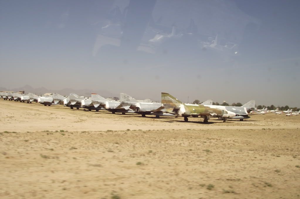
Row after row of old F4 Phantoms--The US doesn't use them anymore, but some of our allies do, so we keep them around for spares and replacement aircraft. Spare part sales help the facility return $11 for every $1 spent.
Note the white sealant around the cockpit windows and other openings. This is to control the temperature inside the plane--keeping it only about 10-15 degrees above the ambient 95 degree weather, as opposed to jumping into ranges like 200 degrees that could hurt the plane. It gave the planes a strange air--I'd never seen anything like it before.
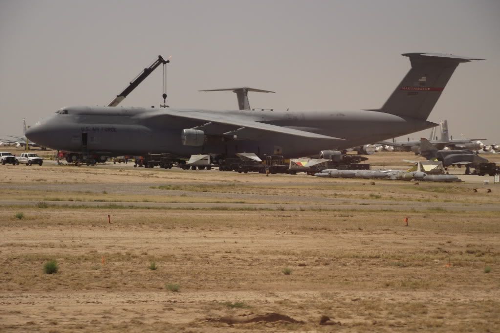
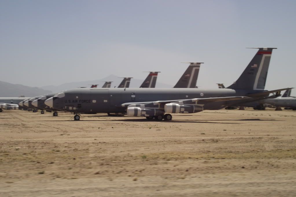
An enormous C-5 Galaxy transport was being processed while we were there--they were removing the  engines for storage, and getting the rest of the plane ready for mothballing alongside 18 others being retired as the new C-17 come into service. Incredible to see the scale of these things, even more to see ten or twelve parked under the desert sun.
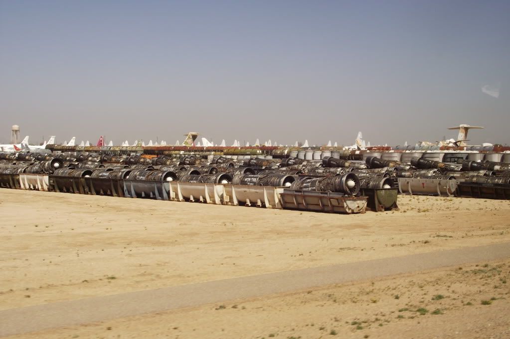
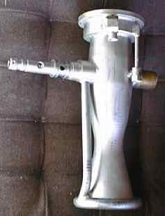
Some engines being stored in canisters. Made me and several other Star Wars nerds think of the pod-racing scenes from Star Wars: A Phantom Menace. Again, very strange sights.
Across the street from the Boneyard was the Pima Air & Space Museum, which I think may now be among my top 3 favorite aircraft museums--the Smithsonian and the USAF museum here in Dayton have more variety, but the Pima museum was designed in a way that every aircraft could really be appreciated close-up, and the lighting and placement of aircraft both inside the hangers and outside on the grounds made it possible to see these planes in a way you can't at the USAF museum sometimes. They also had an interesting variety of one-offs, including a Super Guppy, which was incredible to get to see. The museum also impressed Dr. Altman, which is not an easy thing to do at all--trust me, I know from experience.

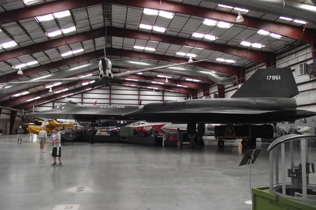
The main hangars were better arranged and lit than the USAF Museum, and though the overall variety wasn't as great, there were some great one-off airplanes.

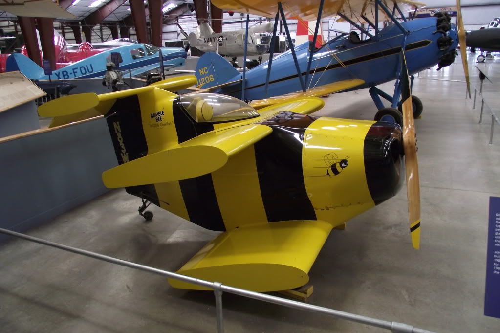
One of these was the Bumblebee II: A biplane specifically designed for attaining the world record for smallest manned airplane. It had a wingspan barely longer than my arm span, and an incredibly low aspect ratio--maybe 2 or 3? Dr. Altman made some comments about the layout of the wings relative to one another, but I can't recall his specific critique. It was funny to think that this thing didn't have much more wing area than our AIAA plane from last year.

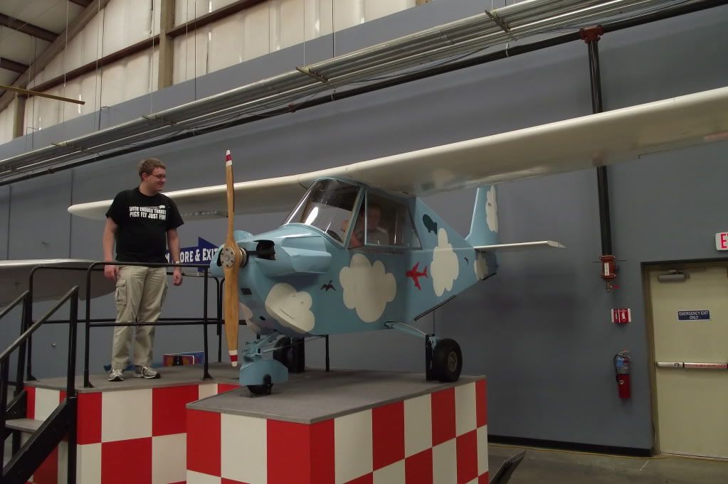
Andrew McClinton (one of two or three members on the team with pilot's licenses) brushes up on his control theory while I look on. This was perhaps not for our precise age group, but Andrew had fun messing with the mobile control surfaces. 
I wish I had more pictures of the rest of the exhibit, which was a strange cross between the oneyard and a normal museum, with historic aircraft parked out under the sun where you could wander around between them. After spending about three hours or so at the Pima museum, we left to catch up with the rest of the team at the competition site. Tech inspection this year was in the same order as the flight order, which made some sense, but it was also going rather slowly. At about 1:30 PM when they started letting teams fly missions, which was another change from last year, when we couldn't fly until Saturday. The extra time ended up helping a lot with everyone getting all their flight attempts in, but the early start and the tech rate meant that around 3:00, they hit the end of the 40 teams that had successfully passed tech (about 50 or so teams processed) and looped around so that at the end of the day, while teams 60 and up had yet to even tech, about 20 teams had already had the chance to fly two scoring missions. In the final analysis, it wasn't so bad this year since the weather was pretty good every day, but if weather had been really bad Saturday or Sunday, this could have been very biasing against the lower-ranked teams.

It was nice to have a chance to walk around and talk to the other teams, though. Several people I'd met previously this year or last year were there, including the OSU DBF team (their first year, and they did pretty well with it) and Wyatt and the other USC team members, who shared a hotel with us last year and this year were a lot of help with issues I'm going to be talking about in a bit. Evening activities included a trip to a very good steakhouse, and heading to sleep early to catch up some from the time changes.

Saturday started off with us finally getting a chance to tech, as some other teams were preparing for their second or third flights. Things largely went well--except for the failsafe system. Competition rules require a system on the aircraft's receiver such that if the plane stops receiving instructions from the controller on the ground, it will automatically enter a death spiral. The organizers do this in the name of the safety of the crowd, but it's rather annoying for those teams that see it trip--it means a simple radio issue can send your plane crashing down in a way that may be basically unrecoverable. Failsafes are common in radio-controlled aircraft, but it's more normal to see them set to have the plane slow down to about 50% speed and hold the last command--stay turning, or continue to fly straight or whatever, partly for the same reason: some competition R/C planes can cost upwards of $1000, and pilots don't want to lose them because of radio issues. Thus, most modern receivers and transmitters are actually incapable of performing the particular failsafe required by competition. This included, as it turned out, our receiver--we couldn't get our rudder to deflect properly for the death spiral. Thus, in order to pass tech, we had to spend almost three hours messing around with our control system, and eventually switching to a totally different transmitter/receiver combination, which was lent to us by USC.

Finally, though, we did pass tech inspection, just as they were about to call our number in the flight order's second rotation. We didn't want to miss another chance, so we began packing up the plane, and hurrying to get to the other side of the judging section just as they called our number. Despite calling to them from only a few feet away, the judge proceeded to call no fewer than four more teams--skipping us for another cycle. Combined with the failsafe issue, tempers started to flare a bit. We managed one flight attempt later in the afternoon, on the next cycle, but a poor hand launch didn't give the plane the right velocity for flight, and it acquainted itself with the ground only a few feet away. Though undamaged and still largely ready-to-fly, the impact broke the propeller and repairs were not allowed, so we'd have to wait another cycle to get into the air. We spent the afternoon using a scale and some statics to verify our static thrust, confirming that it was a launch error and not an issue with the climate difference between Dayton and Tucson, then did some more work on the aerodynamics of flying disc-shaped objects. It looked like we might get one more chance to fly Saturday, but we lost out at the last minute. We'd be close to first Sunday, but...seeing two days down, and not a single successful flight brought morale down a lot, especially since we now had only three remaining flight attempts. To fly all three missions, everything had to go right.

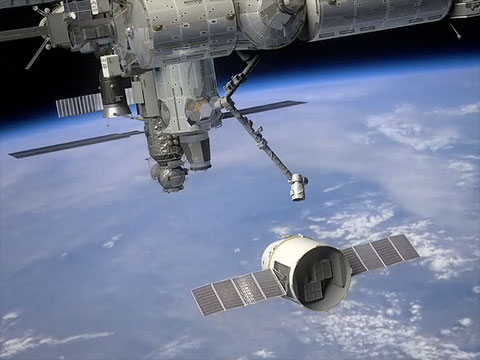
By the end of the day, we were all pretty drained and worn down, but this was altered significantly when some friends of Dr. Altman's family invited us to their place up in the hills. The night sky was amazing--the stars and moon were incredibly clear, and the pool and hot tub were a nice change of pace from the heat. For me, the highlight was when we saw a bright object travel across the sky, from the south-west to the north-east. Dr. Altman said it looked like the trajectory for something in orbit, and Alex Hunton (one of the team's new members, and the guy who took so many of the pictures I've been using through here) wondered if it might be the ISS. I pulled up Heaven's Above on my Pre, and the ground track confirmed it; by complete chance, I'd finally seen what I've been trying for months to see, and the sky couldn't have been better for it. For me, this felt like a good sign for the rest of competition, and for the rest of the team, if the space station didn't do it, the excellent food and the pool helped settle some tempers and sooth frustrations.

Sunday felt a bit strange--because they started flights on Friday instead of Saturday morning, the competition was significantly ahead of previous years. Several teams had already completed all their flights, and others had crashed beyond recovery, so the tent felt oddly empty, and the flight rotation was moving through so quickly that the order began to basically fall apart by afternoon and teams were allowed to fly as soon as they were ready instead of waiting on a rotation. For us, though, the day started off very well--we got to the site right at the start, and moved directly into the assembly area to fly. Leslie Sollman once again assembled well within time, even with time to test the control surfaces, then after waiting behind a few other teams at the flight line, Josh took another try at hand-launching for competition. His throw was better, but it still took a demonstration of supreme skill and confidence on Chris' part to recover when the plane tumbled into a roll off the throw, ending up about 15 feet off the ground and rolled so much that one wing was pointed right at the ground. 4 laps and about 3 minutes later, Chris set the plane down in a perfect belly-landing, and we had a score on the board, moving us from 67th place to 43rd. Considering last year we never managed to get on the board, we counted this as a good start, and stopped for some team pictures.

Left to right: Josh, Cody, Dr. Altman, Me, Kramer, Leslie, James, and Alex
Front Row: Andrew and Steven (the plane)

No, Andrew, your other right.
being on the board took the load off of our shoulders--the goal stopped being "get on the board at all" and proceeded to just "do as well as we can." The second mission was the payload flight, carrying a team-selected 3.81 pound weight, with the goal being the highest payload fraction. Once again, though, simply going out and flying the plane eluded us. The weight was preloaded into the plane before normal assembly, and in the process one of the wires from the receiver came loose. If we'd had our normal receiver, maybe we'd have spotted it, but the failsafe issue means we don't know. Leslie once again did a great job assembling the plane, and we tested the flight controls---except for the throttle. Perhaps you can see where this leads?

So, once again, we left the flight line without flying, bearing a plane almost completely flyable...except for one change that would take all of ten seconds to fix. However, this was around the time they switched to "come when you're ready" instead of a roster, and so we decided to take a breath, check the plane once more for any other issues, get good and ready, then go up for our fourth attempt.  The videos of assembly and the flight for this one are actually posted, so I'll let them speak for themselves.
Leslie Going to Work
Kramer's Hand Launch and the Flight
The first lap may look nerve-wracking on the tape, when the plane only barely got into a stable flight attitude. Let me assure you that having worked so long on that plane and on getting this far, it was pretty much terrifying. This is Cody's video, but notice the shake? All of us were like that this whole flight. However, Chris did another great flight, and we moved from 43rd, to our final position of 63rd with our payload fraction (percent of total weight that was payload) of 47%--one of the highest at competition, though our 4.3 pound empty weight hurt us on the scoring. My guess is that had we managed to fly our third mission with all 37 golf balls we could carry, we'd have finished at least another ten places higher. Ah well--we finished almost 30 place higher than last year, with two scoring flights instead of none, and concluded a very successful design, construction, and flight testing campaign in which we learned a lot. That's a win in my book.

It's getting to within a week of the end of school, and there's a lot of this kind of wrap-up going on. Classes, DBF, finalizing summer plans, and all kinds of other things. Still, if there's one thing I've learned, it's that as every challenge ends, there's always a new one waiting. Part of me can't wait for school to be over, part of me wishes it wouldn't end for another month, and part of me just can't wait for it to be next year already so we could do this all over again. Anyway, so that's the end of this for another year. More space posts to come as I have the time.

Sunday, April 10, 2011

Engineering in Progress goes "Crunch"

So, I go on vacation for the weekend, and what does the team decide to do? Play catch with the plane. And fail on the "catch" part.

Click text for video

Thankfully, this is the V1 prototype (a.k.a. The Hulk), and there is a good reason for all this, so I don't need to yell at someone at the meeting tomorrow, which is nice because I don't really like doing yelling. The idea was to prepare for the testing today, since the weather was poor yesterday. To do this, they loaded the plane to an 8.5 pound total weight (2 pounds heavier than any previous attempt) and practiced hand-launching it. Luckily, catching the plane is not required at competition.

Today saw six hours at the field, and about 10 flights to apply payload testing to the competition aircraft and verify the stuff needed for the Pre-Tech Certification paperwork. I'll put edit some links and more detail in as I know them. Regardless, it feels like we're really ready for competition, and I'm really looking forward to getting to talk to everyone at Tucson. Competition was great last year; getting to hear others talking about solving the same problems our team did in different ways and with subtly different assumptions leading to radically different solutions was very enriching, and I think it helped with our process this year. This year, having been much more involved with the process of design and having the experience of building three different airframes, I think it'll be all the more interesting.

Actually, I know it will for me, I had a taste of it last weekend. At the AIAA Region III Student Conference, I got to talk to some members of The Ohio State team. This is their first year, and they sounded a lot like they were in the same position we were last year in terms of team-building, but their plane still was interesting enough in its approach that I found discussing their approach and comparing ours to be very enriching.

Tuesday, April 5, 2011

Big Rockets and a New Launch Site (For Real)

So, the SpaceX announcement of their new "something big" happened earlier today. It's not quite what I joked about yesterday, but it's still very impressive. In many respects, it's much of what was predicted: Falcon Heavy official announcement, a new launch site at Vandenberg capable of launching the Heavy, and modifications to their launch site at Cape Canaveral to be able to launch the Heavy there too (the current integration building is not large enough for the three-core Heavy). However, as always, the devil is in the details, and in this case, those details are perhaps even more impressive.

Monday, April 4, 2011

SpaceX Announcement Leak: Big Rockets and a new Launch Site

EDIT: The below was posted as my April Fool's joke, a little late. If you're arriving from Google or elsewhere and were hoping for serious updates on the SpaceX Falcon Heavy announcement, try this post instead for my serious reaction to the actual news.

So, there's been a lot of chatter the past week or so about the teaser video SpaceX put out, linked below.


That some element of the Falcon 9 Heavy (now apparently renamed Falcon Heavy, possibly because of the planned switch to a single Merlin 2 engine per core instead of 9 Merlin 1Cs sometime in the future) was going to be announced, and that a new launch site might be involved was also not unexpected (plans for a site at Vandenberg capable of processing the Falcon Heavy have been filed with EPA already, several months ago). However, new leaks (I can't cite sources yet) indicate that this may not be the entire extent of the "something big" coming!

Tuesday, March 29, 2011

At Long Last

Finally, Josh got around to buying the cable he needed to upload all our flight videos, so in a moment that I'm sure will have all of you out there on the edge of your seat, here's the flight videos for the UD AIAA DBF team 2010-2011 season so far. First off, videos from the second round of flights with the prototype on March 20th.
Click Here for Flight 1 Video
Click Here for Flight 2 Video
On March 20th, the prototype made two flights, first with a payload of 1.0 lbs, then with a payload of only 0.5 lbs. These was intended to be empty flights, but some tail-heaviness left us in need of nose weight. In fact, on the 0.5 lbs second flight, the reduction in weight left the aircraft very pitchy in flight. However, the propulsion system was finally reaching a configuration that was a bit more in line with the power and duration that we'll need at Tuscon.

Anyway, so that was a week ago. In the past week, we completed and flew V2, our second aircraft. V2 is almost a pound lighter than the prototype (a 20% weight reduction) and reductions in the tail mean that it doesn't have any of the CG issues which plagued the prototype. We managed two flights on Sunday despite the cold on the field. It may look sunny in the videos that follow. It was sunny, but still cold, to the degree that our flight duration on the second flight was constrained not by the plane but by the pilot's fingers getting too cold to keep flying.

Click Here for Video
For the first flight (video link above), we flew empty, the first properly empty flight we've been able to do all year, thanks to the reductions in weight fixing our CG issues with the prototype. Our normal plane-chucker Kramer Doyle wasn't present, so Josh filled in. On its maiden voyage, V2 did incredibly well--good launch, fast as heck, and no hint of the pitch issues that plagued the prototype. Additionally, we discovered that when in the air, the pinkish wings don't look quite so bad--distance and motion blur cures all wounds, apparently.

Josh with V2, Second Flight. Click this Text for Video
Our second flight of the day was a 2.0 lb payload flight--exceeding our original design goal by almost 0.5 lbs. However, even with this, the weight reductions on V2 meant we were still 0.5 lbs below the maximum flight weight from the prototype. Obviously, we had a bit more drama getting into the air this time--as noted, Josh is not our main thrower, and his co-ordination with Chris wasn't quite perfect. However, the result is impressive. This flight had a 35% payload fraction, and if we load the plane to our maximum demonstrated gross weight from the prototype, we'd have gotten a payload fraction of 42%--well in excess of what we were hoping for during the design face. Originally, the fuselage was designed with enough room for about 50% more golf balls than we were designing the wings to lift, for a few reasons too boring to go into. However, it now looks like not only will we fill that volume, but we might have the capability to lift a few more than that!

In the next week, we're going to be putting together the final competition plane, V3. Again, the construction of a third airframe is new to the team's history, and I'm looking forward to further weight trimming. We should also be able to clean up our wing and tail layups a little and get rid of some of the wrinkles we ran into on V2's wings. I have high hopes for V3, and I'm really looking forward to competition.