Wednesday, June 29, 2011

Free Time? What Free Time?

It's been busy for me, between work and some health issues for my mom, so I haven't had as much time to blog as I might have liked. That's as far as I'll go towards making excuses for my lack of posts the last week or two. However, that's not to say I haven't been working on stuff, just not much and not for very long at a time, and I haven't had any time beyond those work periods to write about them. On that catch-up note, here's an entire project of mine I've yet to even have the chance to talk about here.

About two weeks ago, I was contacted by someone who wanted some help rendering something. You may have heard of the Nautilus-X spacecraft proposal, a design for a long-term reusable orbit-to-orbit vehicle, built in multiple launches using ISS operational experience. The most striking feature for many people is the centrifuge ring, which is spun to create the illusion of gravity. This tends to excite space fans, since centrifuges have this whole air of sci-fi about them, and yet are still plausible, except for all the messy little engineering details like making the plumbing and wiring work across a rotating interface or the effects on maneuvering of essentially having a 30 ton gyroscope mounted to your ship.
Nautilus-X, front perspective view showing centrifuge ring
Nautilus's centrifuge is interesting because it proposes to use inflatable structures for much of the ring. It consists of a rigid hub, connected by a rigid passage tube to a rigid ring section. The ring itself is a mix of such rigid sections linked by inflatable sections (the other two rigid sections are connected by extending trusses to the hub, and serve to help support the ring in spin). Compacted, it's a very tight package, and makes good use of the rigid components where rigid is of benefit and inflatable where inflatable is best. On-orbit, the trusses would extend the ring sections, then the ring would be inflated and fitted out with habitat equipment: sleep stations, communal living areas, perhaps a sickbay or other equipment where gravity would pay off. The idea is interesting, if a bit of what Robert Zubrin would call a "Battlestar," an over-complicated slightly over-built spacecraft, but it's a big dream and I like those. The images of a test centrifuge attached to the ISS as a tech demo especially appeal to me. I've often lamented the loss of the funding for the Centrifuge Accomadations Module, and the lack of really good data on the reaction of the human body to varying gravity levels (including prolonged sub-Earth levels, like a Mars colony might have) and the rotation rates possible before biology and gravity gradients become an issue. With these two pieces of data, it'd actually be possible to design a 2001-style station or a spacecraft like the Discovery (or indeed Nautilus) with some kind of artificial gravity centrifuge.

Demo Centrifuge at ISS
The person who contacted me asked if I might be willing to try to render a conceptual cutaway of the interior of the ring. I used to spend days in middle school doodling diagrams of spacecraft and drawing scale floor plans of them, so this appealed to me, especially since it'd be a nice chance to press my modeling chops. It seemed like a fun thing to try and do--design a possible interior in a relatively small-diameter rotating centrifuge. I should be clear that neither he nor I has any real idea of the internal layout of the Nautilus, I'm not sure one exists at this time, despite all the nifty images of the ISS demo module. Thus, the following is only my best guesses, and as much informed by the design of boats and mobile homes as by valid spacecraft design principles. I hope Winchell Chung can forgive the transgression the previous sentence represents, but it's about the best I can do for the moment. Engineer in progress, it says so in the title.

Anyway, so to start, I needed to establish the physical parameters of the ring. It has been stated in presentations of the concept to have a diameter of 60 feet, and from the image above, scaling from the core (stated in another slide to have a width of 6.5 m), the ring's minor exterior radius looks to be about 4 m or so. Taking into account inflatable walls with a thickness of 16 inches, on the order of Bigelow's designs, this produces an interior diameter of about 134" (Yes, Imperial units. Deal with it. I did.). This gives a volume of around 425 cubic meters, about right for 6 people's occupation for up to two years. It's worth noting that combined with timing this animation of Nautilus (yielding 10 seconds per spin, or 6 RPM), the ship is basically designed to yield Martian gravity: 1/3 Earth gravity.

Cross-sections of Ring
To create the interior of this ring, I defined a flat floor as shown above, based on a minimum overhead of 6 feet. I show a centerline passage of 36" and a passage going past a partitioned room (shown with 36" bed), with 30" of floor space, and some extra elbow room. I then broke down the ring into rooms using these arrangements, and created the design below in Adobe Inventor. The "roof" level is a 78" ceiling: enough to give some head room even for tall people like myself, but not quite towering. With all the area under the floor available for use by utilities, I think that when I get around to modeling a ceiling, it'll be much more of narrow enclosed (?) utility run along the middle than the illustrated flat surface at 78" above the floor, a duct as opposed to a drop ceiling.
Attempt at Nautilus Floor Plan
Click  Image for Full Size
After some refinements and modifications based on discussion with the person who requested the work, I was satisfied enough to begin rendering the ring in Inventor. I rendered each portion (cabins, heads, the mess/galley area, the gym, stowage, the lab and medical bays) separately, so I could assemble them in any order, and so that changes to any on of duplicated rooms like the heads or the cabins would be reflected in all of them with the click of a mouse the next time I opened the assembly. Some rendered animation of the model are below (my first attempt at it with Inventor and it kind of shows--note for future: floors and background should contrast more). I'm hoping to refine both the model and my method of showing it off a bit more, but I'm pretty happy with the start of it. 

View One (Click to play)

View Two (Click to play)

Tuesday, June 14, 2011

Good News and Bad News

So, as the title suggests, I have some good news, and I have some bad news that it'll be bringing with it. The good news is that as I mentioned last post, my summer suddenly became a bit busier than I was worried it might end up. After a lot of job searching, I accepted an offer of a summer position with Ferno-Washington Inc. of Wilmington, Ohio.


Wednesday, June 8, 2011

Imagined Images and Reality

So, you may already heard this (curse my sudden lack of free time!), but the STS-134/International Space Station images are finally in. The image NASA's been promoting the heck out of (and rightfully so, I think) is below, showing the station from the port side, with the shuttle and the station's truss and modules both very visible.

Click image for mondo big version
For those interested, many others from the same astounding  set can be found on the NASA.gov site here. Personally, I think I have enough new backgrounds to last for months if not years. (Also see the video here, for some more amazing content.).

This is truly an amazing and historic moment, but looking at it and thinking about why it is, it reminded me of an image I posted a while back here on Engineer in Progress. No, not Kieth McNeills's amazing model images of what an STS-133 flyaround might have looked like (now with side-by-side comparisons with the real thing on NASAspaceflight's forums here). Something earlier.

Is it the STS-71 Mir image, taken in a similar fashion to the ISS imagery sequence?

No, it's not. It comes from even slightly before that. See below:


That's not the ISS there. That's an artist's conception of the American Space Station Freedom, from the mid-80s to the early-90s, the station which morphed into the core of the American portion of the station. So the Shuttle-docking-to-station image has legs. Why? Because this is what the Shuttle was about, about building and servicing a large space outpost, where various types of science could be performed, from life sciences, materials experiments, astronomy (early SSF proposals included an attached telescope observatory), and technology demonstrations for revolutionary new space hardware (in it's day, they were looking at stuff like solar thermal power generation).

Basically, only in the last few years has the ISS has actually started to do that. The AMS-02 instrument is amazing, but it's only now at the end that it's finally flown. Proposals are circulating to test BEO technologies like VASIMR, inflatible habitats or closed-cycle life support systems on ISS (the ISS water-recycling system is sort of part of that, and that's been going for a few years now, I guess.). And now, finally, after almost 20 years, it's finally happening. That's what I see when I look at the images of Endeavor docked to ISS: the culmination of a 20-year dream.

What's next? Where does spaceflight go from here? I wish I knew. I wish anyone knew--the whole situation with the SLS (Space Launch System, a congressionally-mandated new heavy lift vehicle) is so convoluted, politically-and-emotionally-charged and multi-polar I don't think I can adequately state what the situation is, but it's there. There are also the multitude of dreams offered up by Bigelow, SpaceX, XCOR, Armadillo, Masten, Altius, and many other commercial space companies. In 20 years, which of these dreams will be a reality, and will it take all 20 to make it happen? I wish for as many of the former as possible, and hope not the latter on any. But we'll just have to see. I just wish the space program of the next decade could amaze me and my generation in ways the space program of the last 50 occasionally has amazed past generations, and continues to amaze those of us who care to research it. That's all I want to say, just go back up and enjoy all the links.

Wednesday, May 25, 2011

Mistakes Were Made

Longtime readers (let's pretend for a moment that such a thing exists) of this blog may recall past posts about Bigelow Aerospace, my excitement about their technologies, and my attempts at creating a Transhab Module Calculator capable of roughly approximating possible Bigelow modules. Today, Bigelow broke it's veil of corporate secrecy and allowed a copy of some charts the founder, Robert Bigelow, presented at the International Space Development Conference to be posted at a few sites. Engineer in Progress was not one of those sites, so I can't present that data, but what I can present is this finely-crafted hyperlink to the presentation on SpaceRef, one of the sites that was allowed to post it.

Naturally, after I got done geeking out about the technical details, one of the first things I considered was the specifications presented for the BA-2100 (now dubbed "Olympus," which I think is appropriate for a module that has greater volume than Skylab, Mir, and the International Space Station added together) and whether they fit my calculator's predictions. The results were troubling: the calculator underestimates the module's volume by almost 300 cubic meters, and overestimates the mass by almost 20 metric tons even on my lowest predicted equivalent density.

This error was pretty significant, and so I decided to double-check the calculator against the provided figures for the BA-330. This module was one of the ones I used to calibrate the calculator when I originally created it, so it was perhaps even more troubling that the predictions were also off for the BA-330: The volume was low by almost 100 cubic meters, an underestimate by almost a third.

Therefore, until I've had a chance to look over the new data and diagrams, re-examine my assumed model parameters, and put everything together, I'm retracting the model. I'm going to have to figure out what to do about the calculator (what's wrong, whether I can fix it, and what to do in the meantime), but I wanted to put this out there.

tl;dr: I've found some mistakes in my model based on new data. It's down until I can fix them to my satisfaction.

Monday, May 23, 2011

Been So Long: Soyuz Fly Around at Last!

Well, I know it's been a while since I checked in--I've been busily trying to figure out what I'm going to do this summer. Getting turned down for co-ops all day is hard work. Anyway, I've also been avidly following the STS-134 mission, which featured the installation of the AMS-02 experiment unit on the station truss, and an unexpected but welcome addition: the Soyuz fly-around photo opportunity originally scheduled for STS-133.


On that flight, the Soyuz was the first of a new type, which meant that the Russians did not feel comfortable using it for the proposed photo. However, the Soyuz that is today being used is of the older type, and as a result even as I write this the Soyuz is separating from the station and backing off to take images of the now-finally complete station (well, except for the Russian MLM and node, anyway) and the Space Shuttle Endeavor on that vehicle's final flight. Astronaut Paulo Nespoli will be taking pictures and imagery of the station over the next half-hour or so. For more information, I recommend checking out NASA TV and Nasaspaceflight, my favorite place for space news updates. Engineering imagery of the station from the Soyuz are currently showing on NASA TV, and it's a great prelude of the full images we should get from this unique and historic opportunity.


Soyuz has rolled to re-orient station in camera view, station about to begin a maneuver to give Soyuz a better view of the station. Video apparently also being taken, which should be astounding.


That maneuver now in progress:


Pluming visible on the Soyuz as it maneuvers to keep station.


The imagery from the cameras Nespolia is operating should be amazing, just the engineering views from Soyuz are amazing. Can't wait!

Tuesday, May 10, 2011

I've Been Working on the Railroad

Just to pass the time away, of course. Anyway, I reserve the right to use Engineer in Progress to ruminate on ideas I like, and last night I saw a really interesting one. Ray MacVay, from Blue Max Studios (makers of the hard-scifi RPG Tales of the Black Desert), made an interesting post entitled Artificial Gravity and What Rollercoasters Can Teach Us, and it solidly engaged what someone of my acquittance once called my "turbonerd" mode. The proposal is to use self-propelled train-like cars moving around a fixed circular rail for large spin-gravity spacecraft, instead of a large rotating structure. I'm not really explaining it well, and he does a much better job, so...go read the original post. I'll wait.
Seriously, go check it out. It has pictures.
Done? All right, let's talk the engineering of such a system. First of all, I like a lot about it. Air doesn't need to cross the spin division because entire cars do, presumably each with on-board life support, water reprocessing, and that stuff. Power and data are a bit trickier--unless the cars have their own on-board power generation, then electrical power will still have to be sent to the cars with slip rings, and data will have to be sent from car to car either with a wireless network or (if wired is preferred) another slip ring setup. Still, it's an interesting modular system. Still, there's one or two things that need work.


Monday, May 2, 2011

Not-So-Shiny Metal

Well, the J2X blog has been having some amazing posts and images of their progress in readying the first J2X engine unit for testing, with both the engine and the test stand stand getting close to ready. Hopefully, things will continue to go well, and we might soon see this engine fire, the first good-sized hydrogen/oxygen engine (important for upper stages) to be developed in the US in quite some time. 

J2X engine unit under assembly
Test stand A2, with J2X mass simulator in place
I'm not sold on the need for the J2X or some of the proposed applications. I've heard some arguments for it, I've heard some against, and none have completely convinced me. Still, it's really exciting getting the inside look at the development process that the J2X blog has been offering. The J2X is a modification of the J2, originally developed as the upper stage engine to send the Apollo missions to the moon. However, since changes have taken place in manufacturing techniques and theory in the days since the Apollo program and the J2 has been out of production for almost 35 years, the J2X is less of a modification of an old design and more a new engine that uses the same basic design. One example of this inspired the title of this post, the Shiny Metal post about exploring making use of additive manufacturing techniques to speed up construction and lower costs.

So...what does this all have to with me? Why post about it on Engineer in Progress? Well, it's cool new stuff in aerospace, and I like talking about that. However, it also reminds me of something that I've been working on with the University of Dayton Advanced Rocketry Team (UDART). I've been getting into the organization this year, and the last few days we've been doing some work on our own engine. If you look at my profile picture up on the top right, you'll see me holding the club's LR-101 rocket motor, taken at a presentation they did early in the year before I got involved (actually, that presentation was part of how I ended up getting involved, but that's not worth talking about).


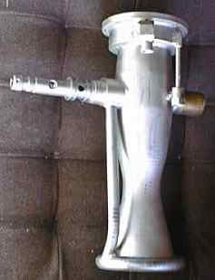
The LR-101 is a liquid rocket engine that burns kerosene and liquid oxygen, and produces about 1,000 lbs of thrust. Just like J2X, the LR-101 has a rich history--while the J2 was developed as an upper stage engine for Apollo, the LR-101 was intended as a vernier steering motor for the Atlas missile--note the welded patches on the combustion chamber where the old gimbal system used to attach (see the image below for what an LR-101 looks like with that).

However, while the J2X is under development and testing to qualify new modifications, we want to test this engine to ensure it's still got enough of the old performance left for the application we'd like to use it in--as the main engine of a sounding rocket intended to reach up to 30,000 feet. To do this, we need to put the engine on a test stand, instrument the engine, and static fire it. The mount at the bottom of the engine in the picture above is part of the mount to the stand. Since I've been a bigger part of the team, I've made getting the test stand ready a priority of mine, and the last few weeks as I've had time away from Aerodesign have paid off handsomely.

UDART LR-101 test stand. Click Image for full size
The entire frame is designed so that we can load it into a pickup truck and move it to a site where we can actually fire the engine, as opposed to our lab next to Five Guys and Panera on Brown Street. At the site, we can then tie it down securely, but the main engine connections and others don't require further work at the site beyond verifying functionality. The way the system works is diagrammed below.

Digram of Propellant Systems
There are three tanks, one of the kerosene fuel, one of the oxygen, and one of high-pressure nitrogen. The nitrogen serves to pressurize the main tanks and force the reactants (the kerosene and oxygen) into the engine to be reacted. To fire the engine, we first open the pressurization valve to bring the tanks to pressure, then open the propellant valves and ignite the engine. The actuators for the valve assemblies can be seen above, though the ball valves themselves are sort of hiding behind the engine mounting plate. A better view of this section can be seen below.

Test stand from upstream. The valve assembly is at the bottom center of the photo.
The valve assemblies have been the focus of work for a while, first getting the pressurization actuator and valve mounted to the stand, and now refitting the main valves and getting them set up. I spent the last two meetings getting the kerosene valve (on the right above) properly and securely mounted to the frame of the stand so that it didn't move and was properly aligned with the oxygen valve next to it. This is required since the two are operated by a single hydraulic actuator--this means that if properly set, the two will be perfectly in-sync, but getting them synced and set up is a lot of work. Saturday, we finished that, mounted the engine as is shown above (including spacers representative of the load cells we'll use to measure the thrust of the engine when we test it), and started work on zeroing the valves.

The valves we use are ball valves, and to ensure proper operation, we have to make sure that the actuator moves them from completely closed to completely open, but doesn't try to go beyond these limits (to avoid deflection of the frame). To do this, we first adjusted the fitting between the actuator rod and the valve rotation link so that it is in the fully closed position when the rod is fully extended, then checked how long the rod needed to be when the valves were fully open. To stop the rod from getting any shorter than this, we have to insert a stopper, shown below.

Spacer/Stopper Rod, Checking Length After Cutting
This consists of a cylindrical piece of metal that goes around the actuator rod. When the rod retracts to the length we want to be the minimum (and corresponding to fully-open valves), the stopper will be stuck between the actuator cylinder and the fitting on the end of the rod, preventing any further retraction. To make this, we took a piece of metal stock that had the right outer diameter, and machined it to have the proper internal diameter. However, while the stock we had did have a hole in it, it was not only too small for the actuation rod to fit through, but in fact too small for the smallest boring bar we had for the lathe to fit into.

Original stock center hole size
Required final inner diameter
Thus, what we had to do was first drill out the center hole with a drill bit, then further increase the internal diameter with the boring bar until the internal hole was large enough to fit around the rod. However, there was one last issue--the boring bar was too short to fit all the way through the stopper size we needed. When we realized this, we had already spent several hours messing with the stand Saturday, so we decided to call it a night instead of taking the time to do the ten or so cuts it would take to do the other side.Thus, tomorrow, we have to turn the stopper around, and finish boring out the last few centimeters of the other side  Actually, the images taken above are of the two ends of the same piece that will become the stopper, so you can see clearly what we have to do. Still, once this is done, we will be able to finalize the actuators, assemble the plumbing to the tanks, and leak test and check the entire system. Then, we just have to take the whole thing apart and clean it to be ready to test. The whole thing is a lot closer to operational than it used to be, and I can't wait to see the job through to static firing.